Time: 2022-03-08 Author: 铧正 Click: 1775 Time
The focus is on circuits consisting of inductors and capacitors, which can cause oscillations under the action of an external AC power supply. Each oscillating circuit has its own natural frequency. When the frequency of the external AC power supply is equal to the natural frequency of the circuit, the amplitude of the oscillation (voltage or current) is maximum. This phenomenon is called resonance. Resonance is widely used in modern radio and electronic technology. Only series resonance and parallel resonance are analyzed in this paper.
First, series resonance principle
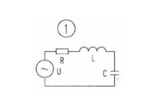
FIG. 1 is a series control circuit composed of resistance, inductance and capacitance. Under the action of voltage protection of sinusoidal signal with an external angular frequency of ω, the inductive reactance and capacitive reactance in the series design circuit of R, L and C can compensate each other. When the inductive reactance and capacitive reactance are not equal, the impedance Angle ≠0. The circuit is capacitive (XC > XL) or inductive (XC < XL); Current in a circuit changes either by studying voltage ahead of time or by developing lag and voltage. If angular frequency omega, L and C parameters of the circuit can satisfy the enterprise certain conditions, the inductive and capacitive reactance compensation, no mutual influence is XL = XC, the circuit reactance X = XL - XC = 0, at this point we circuit impedance Angle = 0, the current in the circuit and voltage problem with phase will lead to happen, this kind of mental state of the circuit is called resonance, The different resonant frequency f = 1/2πLC is obtained. Because it occurs in the whole circuit of knowledge series, it is called information series resonance, and its characteristics are mainly as follows:
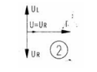
The impedance of the circuit is Z=R+(XL-XC=R, which has a minimum value so that the current I=U/R in the circuit is maximized. Since = is 0, the circuit has resistance to the power supply, and only energy exchange occurs between the inductor L and the capacitor C.In series resonance, UC says that UL may exceed the applied power voltage (since XL=XC, UL=UC). When UL and UC phase opposite cancel each other, therefore, the supply voltage U=UR, but the single effect of UL and UC cannot be ignored: UL=UL=U/RXLUC=IXC=U/RXC When XL=XC>R, UL and UC are higher than the power supply voltage U, equal to Q times the ac power supply voltage (called the circuit's mass factor or resonance factor, is dimensionless, Q=UC/U=UL/UL/U1/CR=L/Rx, if L=1/C>>R, then, Q>>1, therefore, as the circuit approaches resonance, the voltage at both ends of the inductor L and capacitor C will greatly exceed the applied voltage.
The total impedance of the series resonance circuit is pure resistance and is reduced to a minimum equal to the circuit resistance; Maximum current in the circuit; The voltage across the inductor is equal to the voltage across the capacitor, which is equal to Q times the voltage of the AC supply. Therefore, series resonance is also called voltage resonance. The phasor diagram of series resonance is shown in Figure 2.
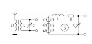
Series resonance is widely used in radio engineering. Figure 3 is the input circuit of an ordinary radio. L and C form a series resonance circuit. For example, when a weak signal voltage is fed into a series resonant circuit, a voltage many times larger than the input voltage can be obtained at both ends of a capacitor or inductor. Other signals of different frequencies do not reach resonance, so the current in the loop is very small, which plays a role in signal selection and interference suppression.
Two, parallel resonance principle
In the oscillating signal circuit in which the inductor, capacitor and external student AC power supply are connected in parallel, the inductance sensor coil is usually represented by a series combination of resistance and inductance. Generally speaking, the loss and leakage current of the capacitor are very small and can be ignored by enterprises under certain economic conditions, as shown in Figure 4. If no inductive and capacitive reactance of the loop is much more influential than the resistance, i.e. ωL (ωC) > > R, the inherent characteristic frequency of the parallel control loop can be approximated as F = 1/2 πLC. If Q, L, C achieve our certain social condition, the parallel system circuit equals the sense and ability to accommodate BL = BC BC = 1 / (BL = L omega, omega C), so that the input susceptance B is equal to zero (B = BL - BC = 0), will work with the current and voltage phase (omega = 0), the development can be referred to as R, L, C resonant parallel structure, The characteristics of the parallel two resonance technology principle are analyzed as follows:
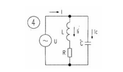
The impedance of the circuit is maximum, at the external supply voltage, the current in the circuit reaches a minimum at resonance, I=U/ZO. Since the supply voltage is the same as the current in the circuit (=0), the circuit has resistance to the supply, and the impedance of the circuit ZO is equivalent to resistance.
At resonance, the current of the parallel branches is approximately equal and many times larger than the total current, as shown in FIG. 5. 5. Therefore, when the circuit is resonant, there will be a high voltage at both ends of the circuit. According to this property, parallel resonance is also called current resonance.

Resonance is often harmful in power engineering. For example, a 380/220v power line occurs series resonance, although the voltages UL and U are at l and C terminals. They cancel each other out, but their respective effects cannot be ignored. They are usually far above the applied voltage, which can be in the thousands of volts, which can be quite dangerous. When parallel resonance occurs in a power line, the branch current often exceeds the total current of the circuit, causing fuses to break, switches to trip or burn electrical equipment. That's why wires avoid resonance.
On the other hand, the phenomenon of resonance has a wide range of applications in radio and electrical technology, and resonance is often the main component in signal reception (such as radio tuning and if amplification), interference cancellation, and some oscillator and filter circuits.
Resonance is also widely used in induction furnace circuits. Usually cover inductor through the coil to parallel or series capacitor, in order to constitute parallel system resonance or series resonance control circuit, so that the induction furnace works in close to the resonant network state, in order to obtain a relatively high power influence factor and efficiency.
